

Viscosity

Kinematic Oil Viscosity Effects On Suspension Damping
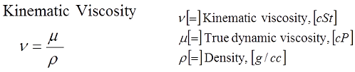
Suspension oil viscosities are reported in terms of kinematic viscosity (cSt@40c and cSt@100c). Kinematic viscosity is defined as the actual oil viscosity (aka the dynamic viscosity) divided by the oil density. That definition has important suspension tuning implications that are often not clearly understood.
Damping performance of a shock absorber depends on both oil viscosity and density:
-
High viscosity (m) oils produce higher friction losses in the suspension circuits. That drives the damping force up.
-
High density (r) oils require more force to push the heavier fluid through the suspension circuits and that drives the damping force up.
High density oils produce more damping force but drive the cSt value of kinematic viscosity down!
![]()
Oil Viscosity Effects On Suspension Damping
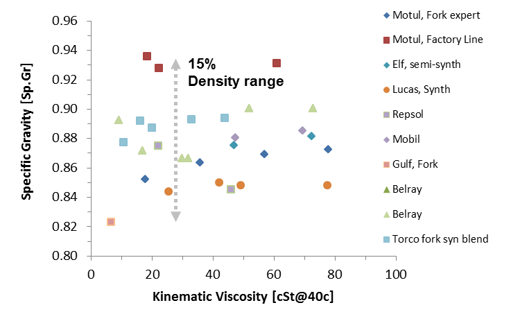
The density of suspension oils vary by 15% from manufacturer to manufacturer. A high density oil will have the same value of kinematic viscosity (cSt) as long as the ratio of viscosity/density is the same. But high density oils will produce more damping force because the fluid weighs more and even more damping force because the viscosity is also higher. Brand-to-brand differences in oil density cause suspension oils with identical values of kinematic viscosity (cSt) to produce different damping forces!
Kinematic viscosity effects on suspension performance becomes even more confusing when comparing different flow circuit geometries. Most suspension use a simple conical tapered needle. Flow losses through the clicker circuit depend on viscous losses through the inlet and flow acceleration losses through the throat. High fluid acceleration at the throat make tapered needle bleed circuits sensitive to changes in fluid density.
-
Tapered Needle: Switching from a low to high density oil requires more force to accelerate the heavier fluid through the clicker needle throat. However, kinematic viscosity (defined as the ratio of viscosity/density) would be lower for the higher density fluid!
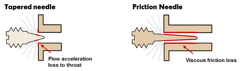
Other bleed circuit configurations use friction needles. Friction needles have a small needle taper. Screwing the needle in increases the length of the high velocity throat region. That increases viscous losses driving damping force up. Friction needles are sensitive to changes in oil viscosity and relatively insensitive to density changes.
-
Friction Needles: Friction needles are sensitive to oil viscosity changes and relatively insensitive to oil density. If you switched to a high density oil the damping force of a friction needle bleed circuit would stay about the same. However, the cSt value of kinematic viscosity (defined as viscosity/density) would go down!
Given nothing but cSt values of kinematic viscosity there is no way to tell if damping force will go up or down. You have to know both the fluid density and viscosity. The ratio of the two tells you nothing. It is also important to note different flow circuit geometries have different sensitivities to changes in oil viscosity and density. Tapered needles and friction needles are an example of that. Knowing the viscosity response of one system is not going to help you guess the response of another. Figuring all of that out is where an analysis tool can really help out.
![]()
Temperature effects on oil viscosity
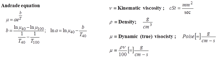
ReStackor evaluates the effect of temperature on oil viscosity using the Andrade equation. Manufacture specs for the viscosity at cSt@40C and cSt@100C along with the spec'd oil density are used to determine the oil dynamic viscosity and the Andrade viscosity coefficients. Those coefficients exactly match the manufacture specs at 40 and 100 C, and provide a reliable relationship to scale oil viscosities across the temperature range.
Viscosity Index (VI), defined by ASTM D 2270-04, relates the viscosity of an oil at 40C and 100C relative to the viscosity of a reference oil at those same temperatures. VI is intended to be a simple reference relating the viscosity fall-off with temperature of one oil relative to another. Oils with a high VI index have lower viscosity changes with temperature.
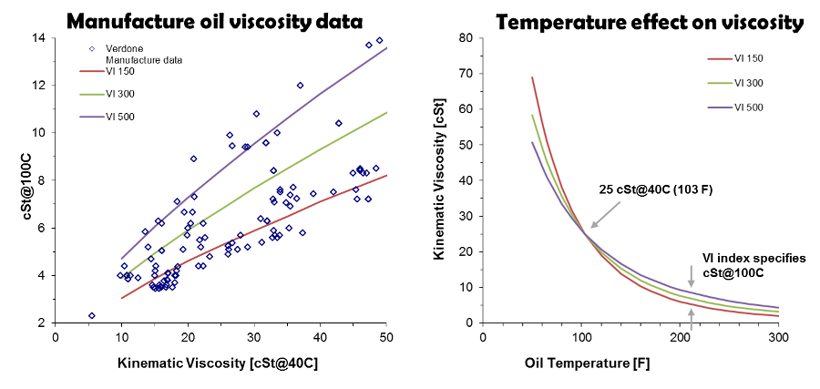
A 25 cSt@40C oil with a VI of 150 would drop to 21% of the initial viscosity at a temperature of 100 C. An oil with a VI of 500 would drop to 34% of the initial value. High VI oils drop less, but it is important to understand the viscosity of oils drop significantly with temperature regardless of the VI index. That creates problems for dyno tuners where small test-to-test changes in oil temperature, by a couple of degrees one way or the other, create significant changes in low speed damping particularly when testing around the 100 F temperature range.
![]()
Hydraulic fluid compressibility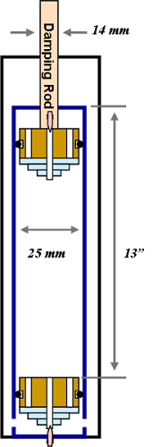
Suspension oil manufactures don't report the compressibility of suspension fluids. The effects can be estimated using the standard rules of thumb for hydraulic system design. For hydraulic systems compressibility result in a volume reduction of 1/2% at 1000 psi, engineers edge .
Assuming a compression chamber length of 13 inches for a fork and a diameter of 25 mm the fluid volume in the compression chamber is 162 cc. If the pressure suddenly spiked to 500 psi oil compressibility would cause the fluid volume to decrease by 0.405 cc. That volume reduction would allow the damper rod to move 0.1 inches due to the compressibility of the oil. The 0.1 inch jump of uncontrolled motion due to fluid compressibility is known as surge in hydraulic systems.
In reality deflection of the seals, expansion of the compression tube and compressibility of foamed oil are larger effects than compressibility of the oil. Hydraulic fluids are, by design, virtually incompressible.
![]()
Hydraulic Fluid Vapor Pressure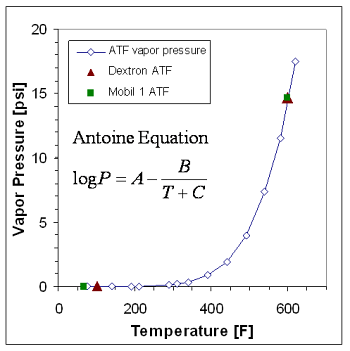
Suspension cavitation limits, cavitation recovery and fluid flow rates through the suspension valves under cavitating conditions are dictated by the fluid vapor pressure downstream of the valve. ReStackor computes fluid vapor pressure as a function of temperature giving ReStackor the capability to compute changes in cavitation limits as fluid temperatures increase under race conditions.
The material safety data sheets available for Mobil 1 ATF gives the vapor pressure at the normal boiling point and at atmospheric conditions. Chevron provides data for Dextron automatic transmission fluid. The combined data can be used to estimate vapor pressure using the Antoine equation (1).
At the normal boiling point of water (212 F) the vapor pressure of ATF is less than 0.1 psi. Oil vapor pressures don't approach atmospheric values until temperatures are in the 600 F range. By design, the vapor pressure of fluids used in suspension systems are very low to help resist cavitation. As long as the shock is below the normal boiling point of water (212 F) the typical assumption of zero vapor pressure is reasonable for estimating shock absorber cavitation limits.
1: Antoine, Compt. rend., 107 (1888)
Hydraulic Fluid Dissolved Gas
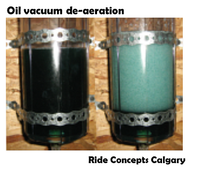
The bigger cavitation issue in suspension systems is controlling the gas dissolved in the suspension oil. Open a fresh bottle of factory sealed suspension fluid and the oil will contain 10 to 15 volume percent dissolved air. The stuff is almost breathable! Pull a vacuum on the oil and the air dissolved in the oil will come boiling out of the fluid.
The fact that gasses dissolve in liquids is not new. There are plenty of examples: soda pop, beer and champagne are all common examples. Another is oxygen dissolved in water, that is how fishies breath under water. Suspension oils are no different. Whenever the pressure is dropped below the initial reservoir pressure the dissolved gases in the oil will come boiling out of the liquid just like opening a hot bottle of coke. The gasses boiling out of the fluid produce a cavitation like event that ends in one of two states:
-
The fluid will reabsorb the gas and return to a clear liquid
-
The fluid will remain as a foamed out hot oil latte
The difference between state one and two depends on how much time the oil is given to recover between suspension strokes. As Roehrig has shown suspension oils are capable of recovering from a foamed out state very quickly after the shaft velocity stops. However, high stroke frequencies on a crank dyno can foam out the oil and not allow the oil to recover between strokes. A principal feature of EMF dynos is the capability to jump to a high shaft velocity in a single stroke which allows investigating the influence of stroke frequency and oil foaming on damping performance.
ReStackor models dissolved air in terms of Ostwald coefficients which measure the volume fraction of gas dissolved in the liquid. If the liquid is allowed to saturate NASA's measurements linked above show Ostwald coefficients for hydraulic fluids range from 0.1 to 0.15. The best approach is to tune the shock absorber base valves and compression adjuster to insure the valves operate under a pressure balanced conditions over the range of operation and do not allow the oil to foam out in the shock.
