

Output file
![]()
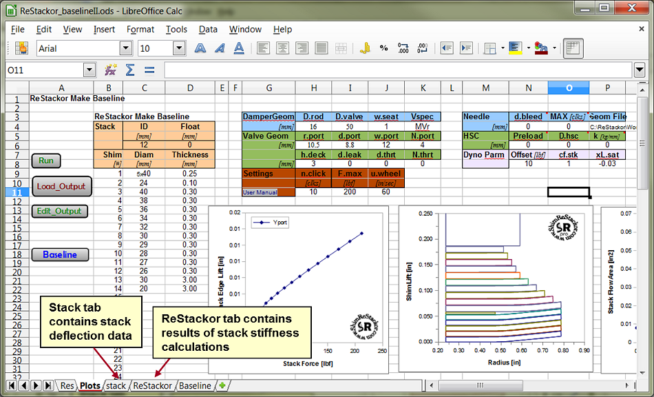
Output File: ReStackor Calculation
-
Sack tab:
-
Shim stack deflection output table describing the deflection of each shim as a function of radial position. Data on the stack tab is used to create the stack deflection plot.
-
-
ReStackor tab:
-
Shim ReStackor: Shim stack edge deflection and flow area as a function of force applied to the stack, columns A through E. Both Shim ReStackor and ReStackor pro compute shim deflection.
-
ReStackor pro: Includes all of the Shim ReStackor outputs plus tables of damping force and chamber pressure as a function of shaft velocity, columns G through H.
-
The definitions of each output parameter are given below.
Simple inputs - thorough analysis - practical results. ReStackor creates a new era of suspension tuning.
![]()
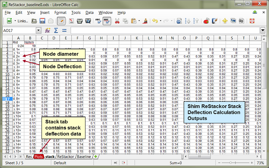
Stack Deflection Outputs
The "stack" tab of the worksheet contains data tables describing the stack deflection. Stack deflection is computed for both Shim ReStackor and ReStackor pro calculations. Data on the "stack" tab is simply a table describing the deflection of each shim in the stack as a function of radial position as computed by ReStackor FEA calculations. The table consists of:
d.n [=] The diameter for each node point for shim N. For the stack computed below ReStackor used 39 node points across the face shim, the data table goes out to column AN, well off the right hand side of the screen shot below.
y.n [=] The deflection height, in inches, of the shim N at the node point d.n.
The ReStackor FEA analysis solves up to 5,000 simultaneous equations to balance the radial and axial forces in the stack. The force balance determines the overall stiffness of the stack and forces necessary to close any crossover gaps in the stack. More details are given on the ReStackor force balance page.
Shim stack deflection output table. Vertical deflection of each shim as a function of radial position.
Data in the above table is far more interesting when viewed as a plot. ReStackor run with: 0; 100 and 200 lbs force applied to the stack face produces the sequence of plots shown below. The plots help visualize the stack structure and the effect of stack changes such as clamp, taper, or crossover gaps on deflection and the shape of the stack stiffness curve.
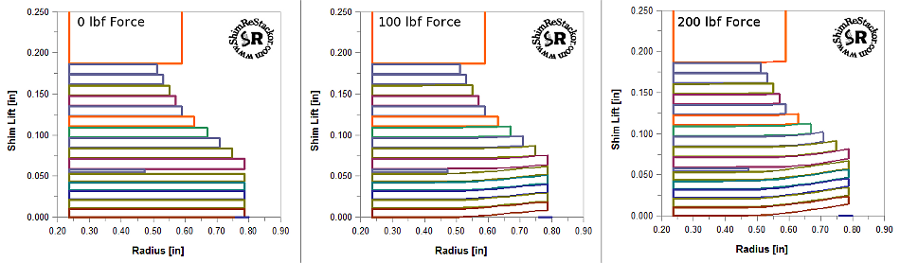
Shim stack deflection plot.
![]()
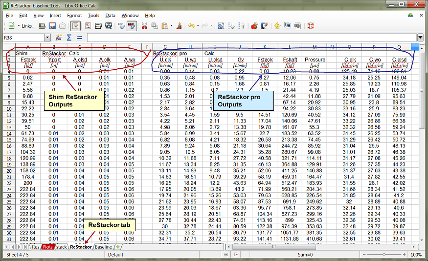
Shim ReStackor Outputs
Shim ReStackor outputs for stack lift as a function of force applied to the stack are loaded onto the "ReStackor" tab of the spreadsheet whenever you hit the "Load_Output" macro button. Shim ReStackor outputs are in columns A through E. ReStackor pro outputs are in columns G through Q.
Valve face flow area and stack deflection outputs for basic Shim ReStackor code.
Shim ReStackor Calculation Outputs, columns A through E:
-
Fstack [=] Force applied to the stack face shim, [lbf].
-
Yport [=] Edge lift of the stack measured at the outer edge of the port, [inches]. The port outer edge radius is given by the input parameters r.port + d.port.
-
Aclsd [=] The fluid flow area between the valve face and stack [square inches]. This measurement is taken with the clickers in the closed position. The fluid flow area depends on the valve port geometry, defined in the input file, and the stack bend profile of the face shim.
-
Aclk [=] The stack flow area [in2] as defined above, plus the flow area through the bleed clickers at the requested clicker position.
-
Awo [=] The stack face flow area [in2] as defined above, plus the clicker flow area at the wide open clicker position.
ReStackor calculations are initiated with zero force applied to the stack. Stack deflections are computed with progressively higher force levels applied to the stack face shim up to the maximum force specified by the input parameter F.stack. ReStackor increments the force using a logarithmic function focusing more points at low force to accurately describe cracking open of the shim stack. Data from the above table is used to construct the Shim ReStackor deflection plots shown on the Plots tab of the workbook.
![]()
![]()
ReStackor pro Outputs
ReStackor pro results are loaded into columns G through M whenever you hit the load output button. The fluid dynamic calculations of ReStackor pro compute the forces and flow losses through the fluid circuits and damping force produced by the shock as a function of shaft velocity.
ReStackor pro fluid dynamic calculations compute damping force as a function of shaft velocity.
Definitions of the ReStackor pro output parameters in columns G through Q:
-
Uclk [=] The suspension damper rod velocity [inches/sec] with the clickers set at the position specified by the input n.click parameter. Using this setting ReStackor pro calculations determine the flow split between the bleed circuit and valve, fluid dynamic forces acting on the shim stack face, resulting stack deflection and fluid flow pressure drop and damping force produced by the shock.
-
Uwo [=] The suspension damper rod velocity [inches/sec] with the clickers in the wide open position. The difference between Uclk and Uwo is the fluid flow through the clicker bleed circuit. With the clickers wide open a higher suspension velocity is needed to make up for the additional flow through the clicker bleed circuit.
-
Uclsd [=] The suspension damper rod velocity [inches/sec] with the clickers in the closed position. The difference between Uclk and Uclsd is there is no flow through the bleed circuit.
-
Gv [=] The fluid flow rate through the combined valve and bleed circuits with the clickers set at the requested position [liters/min].
-
Fstack [=] The fluid dynamic force applied to the shim stack face shim [lbf].
-
Fshaft [=] The damping force produced by the shock absorber [ lbf].
-
Pressure [=] The pressure drop across the valve [psi]. This is the pressure difference across the valve, not the chamber pressure.
-
C.clk [=] Damping coefficient with clickers set at the requested position. The damping coefficient is defined as the shock absorber damping force divided by the shaft velocity [lbf-sec/in]
-
C.wo [=] Damping coefficient with the clickers wide open. [lbf-sec/in]
-
C.clsd [=] Damping coefficient with the clickers closed. [lbf-sec/in]
