

Tuning Basics
Sample Applications

ReStackor Sample Applications
Finally computer software to tune a shim stack
Cavitation in a ICS Motorcycle Fork
ICS systems used in motorcycle forks are an attempt to fulfill two conflicting requirements: The desire for near zero spring force at the top of the stroke to allow the fork to float over small bumps when under hard acceleration, or on a hill climb; Suppression of cavitation through heavy pressurization of the fluid reservoir.
Attempting to satisfy these conflicting requirements requires the use of stiff ICS spring rates and zero preload. Zero preload reduces the fork spring rate at the top of the stroke but produces zero pressurization of the fluid reservoir. This results in a system that easily cavitates at the top of the stroke. Deeper in the stroke, stiff spring rates pressurize the reservoir and force recovery from cavitation. Allowing the fluid circuits to flip into and out of cavitation over the coarse of the stroke results in damping forces that vary dramatically through the stroke. This is the central drawback of an ICS chambered fork.
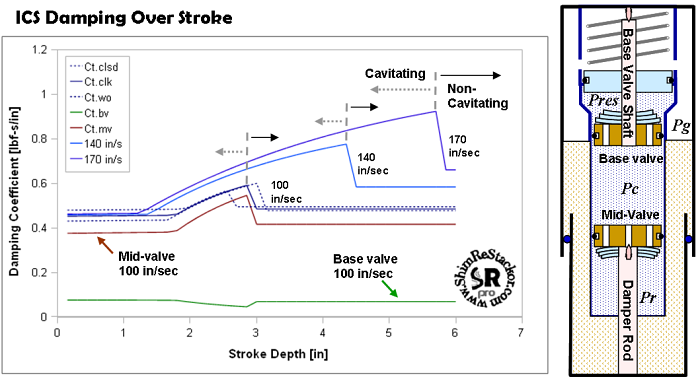
ICS chambered forks cavitate at the top of the stroke creating variations in damping force as the suspension recovers from cavitation deeper in the stroke.
Low pressurization and cavitation at the top of the stroke is an inherent flaw of an ICS systems and cannot be eliminated. Through tuning of the fluid circuits the severity of cavitation can be reduced and the drop-off in damping at cavitation recovery minimized to improve the uniformity in damping force over the stroke.
ReStackor analysis of the process of cavitation initiation, bubble growth, fill and collapse in an ICS chambered fork are detailed here.
-
Cavitation of the rebound chamber during the compression stroke reduces rebound damping producing the feature of riding high in the stroke.
-
Damping forces under cavitating conditions vary with stroke depth and suspension velocity resulting in inconsistent damping forces.
-
Recovery from cavitation deeper in the stroke produces a damping force jump often interpreted by riders as mid-stroke harshness.
ReStackor gives you the capability to understand the cause of each of these effects and the ability to tune it.
![]()
Cavitation
of the Rebound Chamber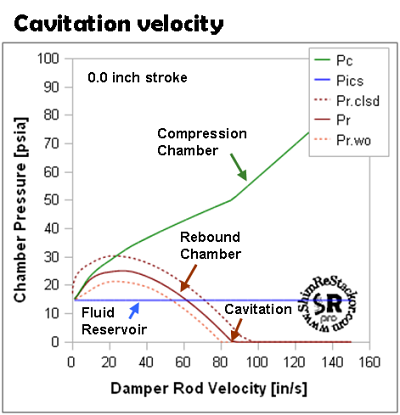
Cavitation limits are a function of the suspension velocity and backpressure produced by the ICS system. Stiff mid-valve shim stacks or low values of stack float cause pressures in the rebound chamber to decrease. If the ICS system is unable to supply the backpressure needed the rebound chamber will cavitate during the compression stroke. This has been videoed by Roehrig. ReStackor computes this same process. At the top of the stroke atmospheric pressure in a ICS system result in cavitation at suspension velocities above 85 in/sec.
Cavitation Recovery
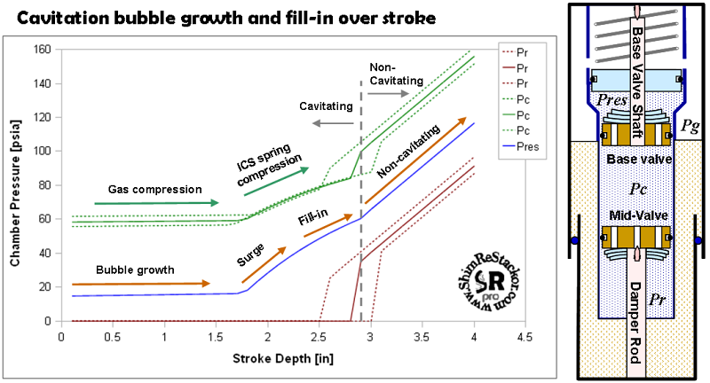
The figure below examines the process of recovery from cavitation as the ICS system builds pressure deeper in the stroke. The calculations examine a four inch stroke at a suspension velocity of 100 in/sec. This suspension velocity is equivalent to a four inch bump hit at 13 mph, not an extreme condition. A suspension velocity of 100 in/sec is above the 85 in/sec cavitation limit at the top of the stroke so the rebound chamber cavitates. Cavitation causes the near zero rebound chamber pressures over the initial portion of the stroke from zero to 2.9 inches.
ICS Reservoir Pressure
The open chamber ICS configuration used in this example shows a gradual pressure rise in the shock fluid reservoir (Pres) as the gas in the fork is compressed over the initial portion of the stroke. At 1.7 inches, float on the ICS spring is consumed causing the chamber pressures to rapidly increase after engagement of the ICS spring. Through this range the mid-valve is cavitated, excess fluid that cannot pass through the mid-valve is forced out through the base valve, as required by the fluid volume balance. The flow surge forces additional fluid through the base valve into the shock reservoir and shortens the suspension stroke depth required to engage the ICS spring. Higher fluid transfer rates caused by the cavitation driven flow surge increases the initial rate of pressure rise produced by compression of the ICS spring.
Base Valve Pressure Drop
At approximately 2.3 inches the back pressure produced by the ICS system is sufficient to force the fluid flow rate needed through the mid-valve to initiate filling of the cavitation bubble. Higher flow rates through the mid-valve results in lower flow rates though the base valve, as required by fluid volume conservation. The lower base valve flow rate results in a decreased rate of pressure rise in the compression chamber as the suspension advances beyond the 2.3 inch stroke depth.
Cavitation Recovery
At approximately 2.9 inches the cavitation bubble in the rebound chamber collapses. While the cavitation bubble is present pressures in the rebound chamber are dictated by the fluid vapor pressure. After collapse, the near incompressible, ridged flow conditions dictated by the mid-valve hydraulic pressure drop set the rebound chamber pressure. The pressure jump at collapse of the cavitation bubble pressurizes the back side of the mid-valve and produces a jump in damping force (more).
Cavitation Control
Reducing variations in damping force over the coarse of the stroke requires filling the cavitation bubble earlier in the stroke before the ICS systems has built large pressures. This reduces the magnitude of the pressure jump and the attendant jump in damping force. Faster filling rates of the cavitation bubble require tuning the shock absorber flow circuits to enable filling of the bubble at the lower ICS pressures present at the start of the stroke.
Calculation Accuracy
Calculation of cavitation limits depends on small differences in large numbers. If the computed base valve pressure drop is off by 10 psi the impact on overall damping force is small. On the other hand, if the base valve pressure drop is 10 psi low and the mid-valve pressure drop is 10 psi high the 20 psi swing in pressure has a large impact on evaluation of cavitation limits. Due to this sensitivity it is unrealistic to expect ReStackor to produce exact answers in a cavitation environment. Your ability to implement and use ReStackor for control and tuning of cavitation depends on your ability to implement the art of suspension tuning ( more ).
![]()
ICS Spring Stiffness
Lack of fluid reservoir pressurization at the top of the stroke in an ICS system results in the formation of a cavitation bubble at the top of the stroke. Softer ICS springs require the suspension to travel deeper into the stroke to build the fluid reservoir pressures necessary to stop growth of the cavitation bubble and develop the mid-valve flow rates necessary to fill the cavitation bubble. The increase in stroke depth required to complete filling of the cavitation bubble with progressively softer ICS springs is demonstrated by the ReStackor calculations below.
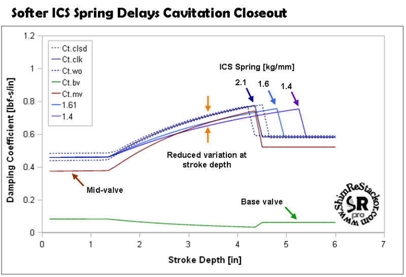
A softer ICS spring delays closeout of the cavitation bubble. The jump in damping force when the bubble closes out is slightly reduced due to the lower ICS pressures.
Softer ICS springs allow the cavitation bubble to grow to a slightly larger volume before the ICS system can build the pressures necessary to stop growth of the cavitation bubble. Softer ICS springs also require a deeper suspension stroke to build the pressures necessary to fill the cavitation bubble. Softer springs spread the entire process out over a longer stroke. Spreading the process out produces a reduced damping force variation at a given stroke depth. At collapse of the cavitation bubble the jump in damping force remains similar.
Reducing float on the ICS spring will initiate filling of the cavitation bubble earlier in the stroke. While effective, this defeats a central feature of the ICS system by increasing the fork spring force at the top of the stroke. The increased spring force can be partially compensated for by exchanging preload on the fork main spring with float reduction on the ICS spring to maintain a similar initial spring rate.
By spreading the cavitation bubble filling process out over a longer stroke softer ICS springs reduced the apparent damping force variation at a given stroke depth, but the jump in damping force at collapse of the cavitation bubble remains similar. There is a better fix .
![]()
Mid-Valve Float
Increasing float on the mid-valve stack reduces the low speed flow resistance and allows the cavitation bubble to fill earlier before the ICS system has reached high pressures. This reduces the magnitude of the damping force jump at collapse of the cavitation bubble and the variation in damping force over the stroke. Investigation of the effect of stack float shows the source of the problem for the crf450 mid-valve configuration used in this example problem.
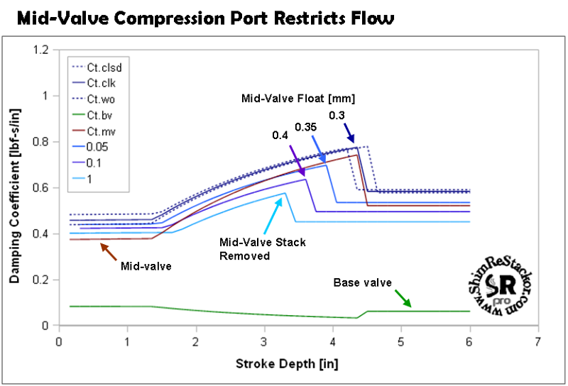
Mid-valve compression ports on a crf450 are two small to allow the fluid transport necessary to close out the cavitation bubble at the start of the stroke.
Problem identification
With the shim stack completely removed the crf450 mid-valve cannot produce the fluid flow rate necessary to fill in the cavitation bubble at a modest suspension velocity of 140 in/sec. Deeper in the stroke, at approximately 3.25 inches, the ICS system builds the reservoir pressures necessary to closeout the cavitation bubble. Flow restrictions of the crf450 mid-valve compression port also effects tuning of a weight scaled shim stack.
![]()
Cavitation Control
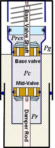
Gaining control of mid-valve cavitation and accelerating the filling process of the cavitation bubble requires higher fluid flow rates through the mid-valve. There are two options: Decrease the flow resistance through the mid-valve; Increase fluid pressures in the compression chamber to force higher mid-valve flow.
-
Mid-Valve Flow Resistance:
-
Shim stack: With the shim stack completely removed ReStackor calculations show the flow resistance through the mid-valve port is too high to enable filling of the cavitation bubble. Shim stack modifications cannot reduce the mid-valve flow resistance.
-
Valve port modifications: Inspection of the crf450 mid-valve shows the compression ports are already near the maximum practical port flow area. Further increase port area is not possible without restricting flow through the rebound ports.
-
-
Fluid Pressure: There are two options to increase compression chamber pressures in the shock.
-
Increase pressures from the ICS system: The central feature of the ICS system in a motorcycle fork is zero pressurization of the reservoir and zero spring force at the top of the stroke. Attempting to control cavitation initiation at the top of the stroke through pressurization of the ICS system defeats the central feature the system.
-
Increase base valve flow resistance: Increasing flow resistance through the base valve increases the compression chamber pressures and the pressures at the mid-valve face. Higher pressure suppresses cavitation. Increasing the base valve flow resistance increase the shock damping force and allow less restrictive mid-valve shim stack to be used further improving the capability of base valve flow resistance to suppresses cavitation.
-
Increasing the base valve flow resistance is the single viable choice for controlling mid-valve cavitation at the top of the stroke.
![]()
Base Valve Tuning For Cavitation Control
Increasing flow resistance through the base valve increases pressures in the shock compression chamber and the fill rate of the mid-valve cavitation bubble. This can be achieved through modifying the digressive damping curve shape of the stock base valve to increase damping forces at higher suspension velocities. Modifying a digressive damping curve to produce a more linear profile requires lower oil viscosity, smaller valve ports and modifications to the shim stack. Achieving the desired increase requires implementing all three of these options.
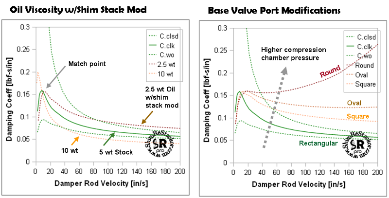
ReStackor pro gives you the capability to evaluate oil viscosity effects and tune valve port geometries to control the shape of the damping force curve.
Decreasing oil viscosity from the stock 5 wt oil to 2.5 wt and modifying the shim stack to maintain the same damping force peak moves the damping curve toward a linear profile. This is the effect needed, but insufficient magnitude. Achieving the magnitude desired requires modification of the valve port geometry. Starting from the rectangular pie shaped segment of the open port stock valve the port area was reduced to a square shaped port. The reduced flow area produces a corresponding increase in high speed flow resistance. Further reducing the port flow area using a simple round port results in a progressive damping profile. For the calculations here an oval shaped port provides the damping profile desired. Other port shapes could be used provided appropriate modifications to port flow area and shim stack configuration for each port shape.
The increased flow resistance through the base valve forces higher pressures in the shock compression chamber and higher flow rates through the mid-valve. The higher pressures fill in the cavitation bubble earlier in the stroke suppressing cavitation effects and variations in damping force. Tuning the base valve flow resistance to control cavitation produces a uniform damping force over the entire stroke.
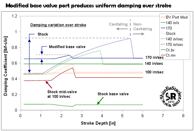
ReStackor modifications to base valve port increase pressures in the compression chamber and suppress cavitation effects on damping force variations over the stroke.
At suspension velocities of 100 and 140 in/sec cavitation effects are eliminated at the damping force over the entire stroke is uniform. At a suspension velocity of 170 in/sec a small cavitation bubble is formed and collapse of this bubble at an approximately stroke depth of two inches causes a small damping spike. This is a significant improvement over the stock configuration. Further tuning of the base valve flow resistance could be made to eliminate this spike.
At higher suspension speeds the increase in mid-valve pressure drop will eventually cavitate the rebound chamber. The suspension velocity where this occurs at suspension stroke depths of four and six inches can be easily spotted in the ReStackor suspension velocity plot. Modifications to the base valve flow resistance significantly extend the operation range of the suspension and decrease the magnitude of the damping spike when the suspension is driven beyond the cavitation limit. These effects are completely tunable by the calculations of ReStackor.
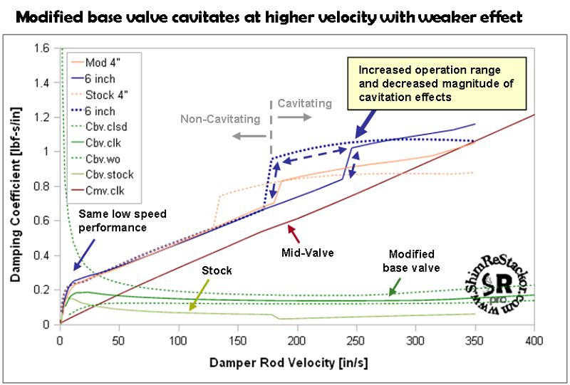
ReStackor gives you the capability to control cavitation effects, tune suspension velocities where caviation occurs and control effects on damping force variations over the entire range of suspension operation.
To achieve these results both the base valve port diameter and shim stack were modified. Modifications to the shim stack allow the low speed damping forces to matched with the stock rates. Modifications to the port diameter and mid-valve stack allow the mid-speed damping rates of the stock configuration to be matched. The base valve port modifications produce a nearly linear damping force curve and much higher pressures in the shock compression chamber above suspension velocities of 20 in/sec. This suppresses cavitation of the mid-valve to velocities of 250 in/sec. A substantial improvement over the stock configuration which cavitates at suspension suspension velocities of 170 in/sec and produces a much large damping spike at the cavitation limit.
Simultaneous tuning of multiple parameters is far easier with and analysis tool than anything you could hope to achieve by the old cut-and-try method. In this example increased base valve damping was exchanged with decreased mid-valve damping. This maintains the same overall damping rate and increases pressures in the shock compression chamber to control cavitation. Simple by analysis, nearly impossible by the seat-of-the-pants.
-
ReStackor gives you the capability to understand the influence of each component in the shock.
-
Simple plots allow the cause of cavitation to be easily understood.
-
Understanding of the cause allows fixes to be identified.
-
Each of those fixes can be tested in ReStackor to determine the best option.
-
-
Simultaneous parameters were tuned to achieve the desired results.
-
Base valve oil viscosity, port diameter and the shim stack were tuned to produce the necessary compression chamber pressures for cavitation control.
-
Mid-valve shim stack stiffness and float were tuned to maintain the stock damping rates.
-
The capability to identify the cause of suspension performance problems and simultaneously tune multiple parameters to control a single effect gives you the capability to tune your suspension far beyond the limits previously possible.
![]()
Mid-Valve Cavitation Control
Tuning suspension systems near the cavitation limit can be frustrating. Controlling cavitation is simple and only requires pressures to be above the fluid vapor pressure. Controlling chamber pressures is the hard part and requires the base valve stack stiffness, mid-valve stiffness, stack float, and backpressure of the ICS system to all simultaneously operate within the cavitation limits while producing the damping rates desired.
Simultaneous control of even two parameters can be nearly impossible when tuning by the seat-of-the-pants. Months have been spent dyno testing shim stacks and ICS combinations searching for that magic configuration that produces acceptable damping and operates just above the cavitation limit. Under race conditions, higher oil temperatures change the cavitation limit and the shock no longer performs. Tuning frustrations could eventually lead you to construction of a glass shock absorber, as in the case of Roehrig, for the simple purpose of demonstrating cavitation limits and its influence on shock absorber performance. The cost of this approach is far beyond suspension tuners and most factory race teams.
ReStackor offers a far more effective and productive approach. Through modeling of the physical flow processes occurring within the guts of the shock ReStackor gives you the capability to understand operation of the shock, the influence of each component in the shock and the capability to tune those components to control shock absorber performance. Using simple plots of the chamber pressures cavitation limits can be easily understood. With an understanding fixes can be identified, the tuning modification needed determined and tested over the entire range of suspension speeds to insure those modifications do not produce an unexpected side effect. If that occurs multiple parameters can be simultaneously tuned to mitigate the side effects.
Whether your suspension is analytically perfect -or not- it all comes down to how it rides. If test rides identify your bike produces some suspension anomaly ReStackor gives you the capability to analyze your suspension on that specific bump height to determine the source of the suspension behavior, the influence of each component and the capability to tune that component to eliminate or exploit the suspension behavior. The capability to tune your suspension "in-situ" under the actual ride conditions, speeds and terrain that you ride gives you the capability to tune your suspension far beyond the limits previously possible.
That combination of test and analysis produces the most powerful tuning tool possible. ReStackor introduces a new era in suspension tuning.
