

Spreadsheets
Plots
![]()
ReStackor User Manual
Finally computer software to tune a shim stack
Mid-Valve Damper Tuning Plots
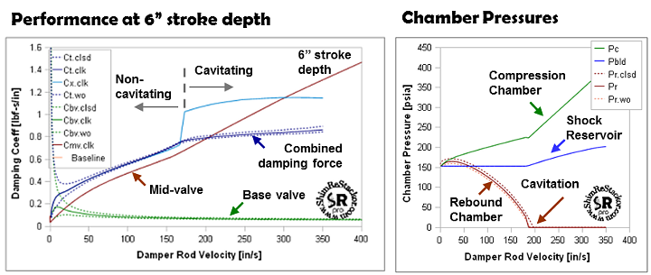
The two figures below show the bottom line of ReStackor mid-valve analysis. The first figure shows damping force as a function of suspension velocity, the second figure chamber pressures. Damping performance, cavitation limits and the effectiveness of bladder or ICS systems are all shown by these two plots.
ReStackor_midvalve.xls spreadsheet computes the combined damping force and cavitation limits of a mid-valve setup.
Mid-valve compression damping performance depends on the stiffness of the base valve shim stack, mid-valve stack and the interaction of those two valves with the reservoir pressurization system. Understanding the influence of these systems on the overall damping performance gives you the capability to tune each of these systems to control the shape and magnitude of the damping force curve over the entire range of suspension velocities.
The influence of each of these systems on the shape of the damping force curve are discussed below.
![]()
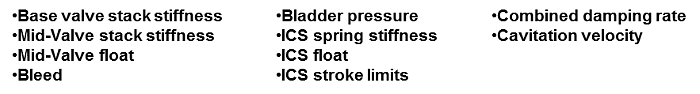
Bladder Pressurized Reservoir
Cavitation in the fluid circuits of a shock is unavoidable. Pressurized bladders and ICS systems are used in shock absorbers to help the oil recover from a cavitation event and minimize the effects of foamed oil from a single cavitation event on subsequent strokes of the shock.
The capability to recover from a cavitation event depends on the pressure in the down stream chamber of the shock. High pressures allow the oil to quickly reabsorb the foam, low pressures allow the foam to carry over into subsequent strokes of the shock effecting performance. On the compression stroke the minimum chamber pressure occurs in the rebound chamber. Controlling pressures in the rebound chamber is the key to minimizing cavitation effects in a shock.
Rebound chamber pressures are controlled by three tunable elements:
-
Reservoir pressure: Set by the initial charge pressure of the bladder and the volume of fluid transferred to the reservoir which further compresses the bladder.
-
Compression chamber pressure: Set by the reservoir pressure minus the pressure drop through the base valve shim stack and bleed circuit.
-
Rebound chamber pressure: Set by the compression chamber pressure minus the pressure drop through the mid-valve shim stack and bleed circuits.
As an equation the rebound chamber pressure is set by:
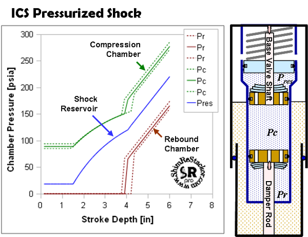
The ReStackor mid-valve.xls spreadsheet computes each of these chamber pressures and allows you to tune each flow circuit to see the effect on the overall system. The example below shows all three chamber pressures.
Reservoir pressure: For this example chamber pressures were computed at a constant damper rod stroke of two inches. The damper rod stroke sets the volume of fluid transferred into the reservoir. The fluid transfer compresses the bladder and causes the reservoir pressure to increase from the initial gas charge of 140 psia to 150 psia.
 At
shaft velocities above 190 in/sec the mid-valve cavitates. When cavitated, flow that can not pass through the mid-valve is forced out
of the shock through the base valve. This cavitation driven flow surge into the
reservoir creates the reservoir chamber pressure increase at shaft
velocities above 190 in/sec.
At
shaft velocities above 190 in/sec the mid-valve cavitates. When cavitated, flow that can not pass through the mid-valve is forced out
of the shock through the base valve. This cavitation driven flow surge into the
reservoir creates the reservoir chamber pressure increase at shaft
velocities above 190 in/sec.
Increasing the gas charge pressure to 200 psia would backpressure all of the chambers, prevent the mid-valve from cavitating and prevent the cavitated flow surge shown in this example.
Compression chamber pressures: As the damper rod is forced into the shock, fluid is forced out of the shock through the base valve into the fluid reservoir. As shaft velocities increase, the volume of fluid flowing through the base valve increases creating a steady rise in compression chamber pressures with shaft velocity. Above shaft velocities of 190 in/sec the mid-valve cavitates. Excess fluid that cannot pass through the mid-valve is force out of the shock through the base valve. The cavitation driven flow surge through the base valve creates the sharp rise in compression chamber pressures above shaft velocities of 190 in/sec.
For this example, increasing the base valve shim stack stiffness would increase pressures in the compression chamber and delay cavitation of the mid-valve.
Rebound chamber pressures: From shaft velocities of zero to 25 in/sec the flow resistance through the base valve is greater than the flow resistance of the mid-valve. This causes the pressures in the rebound chamber to go up. As shaft velocities further increase the flow resistance through the mid-valve increases faster than the base valve and pressures in the rebound chamber drop. When chamber pressure drops below the reservoir pressure gas dissolved in the oil will begin to be released foaming the oil. When the chamber pressure drops below the oil vapor pressure a vacuum cavitation bubble will form increasing the severity of cavitation and the resulting flow surge.
The shaft velocity where cavitation of the mid-valve initiates can be changed by altering the mid-valve shim stack stiffness. Increased stiffness will cause the mid-valve to cavitate at a lower shaft velocity. Decreased stiffness or increased bleed will cause the cavitation velocity to increase.
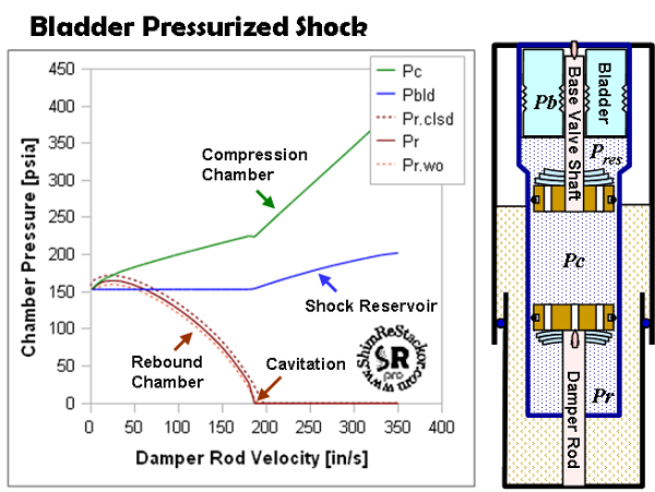
Valve Pressure Drop
The
mid-valve compression shim stack is typically much softer then the
base valve stack. Due to the
softer stack little damping
force
is produced
by the mid-valve at low speed.
As
suspension speeds increase, higher oil flow rates through the mid-valve
produce a rapid increase in damping force
as
well
as
pressure drop across the mid-valve.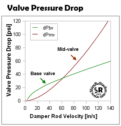
Plotting the pressure drop across the two valves helps in understanding the cavitation limits and behavoir of a particular setup. For the example here, the pressure drop across the base valve is larger than the mid-valve for shaft velocities below 60 in/sec. Over this range the high base valve pressure drop is going to backpressure the whole system and prevent cavitation.
At a damper rod velocity of approximately 60 in/sec the pressure drop across the mid-valve matches the base valve. Above this shaft velocity the mid-valve pressure drop becomes much greater. When the mid-valve pressure drop is greater then the pressure drop across the base valve the pressure in the rebound chamber is going to drop. When the rebound chamber pressure falls below the vapor pressure of gas dissolved in the oil the gas will start to boil out of the oil and foam the fluid. This is the start of cavitation.
![]()
ICS Pressurization
The cavitation behavior of an ICS system is different than a bladder pressurized system. At the top of the stroke the fluid reservoir is under low pressure in an ICS system. As the system is driven into the stroke fluid is transferred into the reservoir, the ICS spring is compressed and the reservoir pressure builds. Lack of reservoir pressure at the top of the stroke result in a suspension that easily cavitates at the top of the stroke. As pressure builds deeper in the stroke the suspension recovers from the initial cavitation. The process of an ICS system flipping into and out of cavitation over the coarse of a stroke produces a number of unusual effects in a ICS chambered fork (ReStackor Web Site).
Example ReStackor ICS Calculations
For
the example calculation here the ICS spring is installed with a small
float so there is no ICS spring force on the wheel at the top of the
stroke and the reservoir is bleed to an initial fork pressure of 14.7 psia.
 Over the first 1.5
inches of stroke
there is little change in the
reservoir pressure due to the ICS spring float. Beyond 1.5 inches
the ICS spring engages pressurizing the reservoir and the shock
compression chamber.
Over the first 1.5
inches of stroke
there is little change in the
reservoir pressure due to the ICS spring float. Beyond 1.5 inches
the ICS spring engages pressurizing the reservoir and the shock
compression chamber.
With no pressurization of the fluid circuits at the top of the stroke the rebound chamber cavitates at the start of the suspension motion. This cavitation is caused by the stiffness of the mid-valve shim stack. With the stack closing off the valve ports the mid-valve can not deliver the fluid volume necessary to keep the rebound chamber filled with fluid. Due to the insufficient flow a vacuum cavitation bubble forms in the rebound chamber resulting in the near zero pressures shown. Preventing rebound chamber cavitation requires higher pressures in the shock compression chamber (Pc) to force the volume of fluid necessary through the mid-valve and keep the rebound chamber filled with fluid.
As the suspension is driven deeper into the stroke pressures produced by the ICS system increase. The pressure in the rebound chamber remains fixed at the vapor pressure of the hydraulic fluid as long as the cavitation bubble is present in the rebound chamber. This produces a high pressure drop across the mid-valve which helps to rapidly fill in the cavitation bubble. While the cavitation bubble is filling the high pressures produced by the ICS system act directly on the face of the mid-valve and react a higher then normal damping force to the damper rod. When the bubble is completely filled pressures in the rebound chamber suddenly spike up. The spike is caused by the jump from the near vacuum conditions of the cavitation bubble to the near incompressible hydraulic flow conditions of non-cavitating flow. This pressure jump pressurizes the back side of the mid-valve and causes a corresponding jump in damping force.
While the cavitation bubble is filling , flow rates through the mid-valve are increased. Higher flow through the mid-valve results in a decreased flow through the base valve. The steadily decreasing base valve flow created by filling of the cavitation bubble produces the arc like shape of the compression chamber pressure profile from 1.5 to 3.9 inches. Once the cavitation bubble has completely filled the flow rates through the suspension circuits sharply jump to the near incompressible conditions of hydraulic flow. This restores the flow through the base valve and results in a sudden jump in the base valve pressure drop as shown in the plot.
![]()
Suspension Velocity Effects On ICS Cavitation Limits
Cavitation
behavior in an ICS fork is a function of both suspension velocity and
stroke depth. High suspension velocity increases cavitation. A deep
suspension stroke transfers more fluid to the reservoir increasing the
reservoir ICS pressure and reduces cavitation. 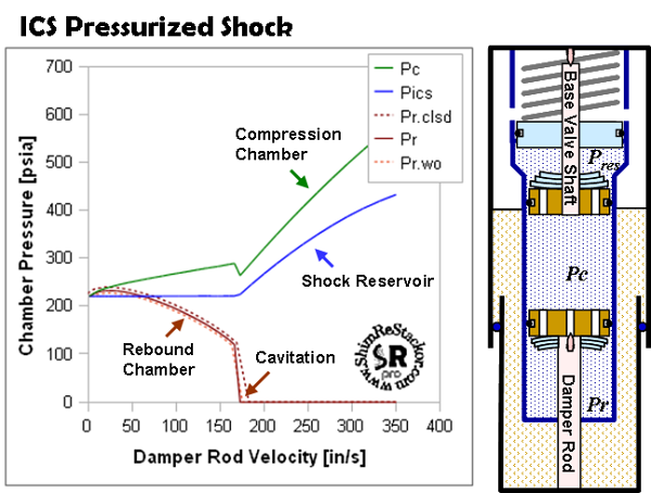 For
the six inch suspension stroke
used in this example the ICS system cannot recover from cavitation at
suspension velocities above 170 in/sec.
For
the six inch suspension stroke
used in this example the ICS system cannot recover from cavitation at
suspension velocities above 170 in/sec.
Below velocities of 170 in/sec the suspension initially cavitates then recovers from cavitation as the ICS system builds pressure when the suspension is driven deeper into the stroke. Above the velocities of 170 in/sec the six inch suspension stroke depth cannot build the reservoir pressure necessary to backfill the cavitation bubble and recover from the initial cavitation event. For this setup the cavitation limit is 170 in/sec. Above that speed the fork will not recover from the cavitation event at the start of the stroke.
When cavitated, the flow surge created by the cavitated mid-valve pushes additional fluid into the shock reservoir. The increasingly larger flow surge as the shock is driven above the cavitation limit creates the continuous increase in shock reservoir pressure due to compression of the ICS spring. Pressures in the shock compression chamber step down slightly at the jump from non-cavitating to cavitating conditions. This step in pressure is caused by the reduced flow through the base valve when the cavitation bubble is filling. As the suspension is driven further away from the cavitation point the cavitation bubble shifts from the filling process to the growth process creating the step in compression chamber pressures shown. (more, ReStackor Web Site).
