

Valve Geom
Valve Port Geometry
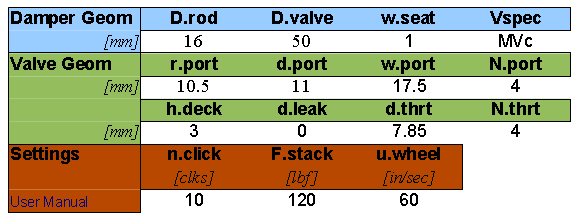
Parameters defining the valve port geometry and calculation conditions of shaft velocity, clicker settings and maximum force to be applied to the shim stack.
![]()
Damper
Geometry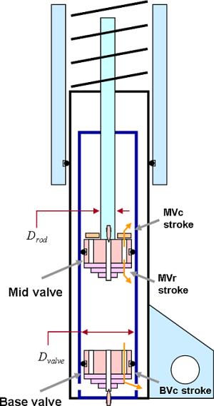
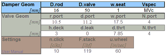
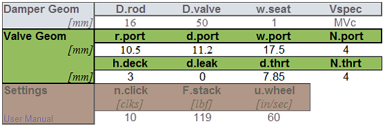
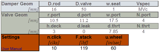
The damper geometry block specifies the basic shock dimensions. There are four parameters:
-
D.rod [=] The shock absorber damper rod diameter in millimeters.
-
D.valve [=] The inside diameter of the shock absorber body in millimeters.
-
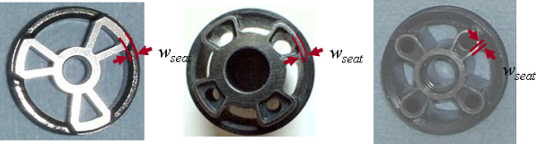
w.seat [=] The seat width of the valve ports in millimeters.
-
Vspec [=] The keyword Vspec specifies the stroke direction:
-
BVc [=] Base valve compression.
-
MVc [=] Mid valve compression stroke.
-
MVr [=] Mid valve rebound stroke.
The Vspec keyword is also used to get your user key, input your code key and get the version of ReStackor you are running.
-
Ukey [=] Pop-up execution window will show your User key.
-
Ckey [=] Pup-up execution window will prompt you to enter your code key purchased through PayPal.
-
ver [=] Pup-up execution window will show you the version number of ReStackor you are running.
-
----------------------------------------------------------------------------------------
Suspension Stroke (BVc, MVr, MVc)
There are two types of valves in shock absorbers: mid-valves and base-valves. The base valve, or compression adjuster, is generally located on the opposite end of the shock from the damper rod entrance. As the damper rod is forced into the shock, fluid is forced out through the base valve into the fluid reservoir. Since the damper rod has a small diameter the flow rate through the base valve is very small. The base valve is usually used for compression damping and is specified in ReStackor by setting the Vspec keyword to BVc.
A mid-valve is located on the end of the damper rod. As the damper rod is forced into the shock fluid is forced through the mid valve to fill in the volume behind the valve. On compression stroke, MVc, the entire face of the mid-valve is pressurized. On the rebound stroke, MVr, only the annulus between the damper rod and valve OD is pressurized. Setting Vspec keyword to MVc (mid-valve compression), MVr (mid-valve rebound) or BVc (base valve compression) sets ReStackor to run the different strokes.
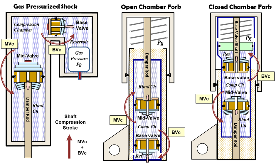
Fluid flow direction on the mid-valve compression, MVc, and base valve compression, MVc, stroke.
----------------------------------------------------------------------------------------
User Key
ReStackor also uses the Vspec keyword to get your user key and enter your code key. To extract your user key set the Vspec keyword to Ukey, hit the run button and the pop up execution window will show your user key.
ReStackor code keys are purchased through PayPal, enter your credit card info and at checkout the confirmation page will prompt "-- CLICK Here to enter your user key". Click the prompt, enter your user key and your companion code key will be emailed to you.
To enter your code key set Vspec to Ckey, run the code and the pop-up execution window will prompt you to enter your purchased code key.
Vspec code key entry:
Ukey [=] The pop-up code execution window will show your user key. You will need to enter this key at PayPal checkout to get your code key.
Ckey [=] The pop-up code execution window will prompt you to enter your code key purchased from PayPal.
![]()
Valve Geometry
The
valve geometry input block describes the
dimensions
of
the
valve port.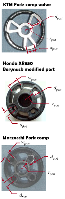
-
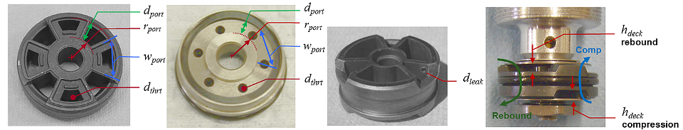
r.port [=] The radial distance from the valve center to the inside edge of the valve port in millimeters. This parameter defines the inner radius of the shim stack face pressurized by the valve port.
-
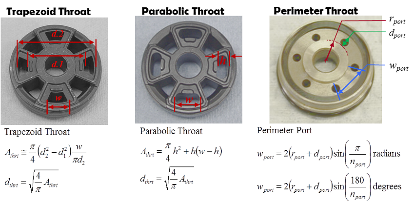
w.port [=] The valve port width in millimeters. W.port is measured at the outer edge of the port and is the width from inside edge to inside edge of the valve seat. Large values of w.port increase the flow area at the stack perimeter and reduce the valve flow resistance. Also, see the perimeter port example below for calculation of w.port on a compression adjuster.
-
d.port [=] The radial length of the valve port in millimeters. This parameter, coupled with w.port, describes the flow area of the valve port. The sum of r.port plus d.port and the valve seat width, w.seat, must be less than or equal to the valve diameter. If not, the code will kick you out with an error message.
-
N.port [=] The number of valve ports. The Honda and Marzocchi valves shown above have four ports. The KTM valve has three ports.
-
h.deck [=] Port entrance deck height in millimeters. At the entrance to the valve port
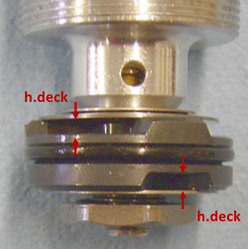 the
deck height between the reverse flow shim stack and valve face
create a flow restriction. ReStackor uses h.deck*w.port to determine the
available flow area. Delta shims on the reverse flow shim stack can be used to
raise the deck height and reduce h.deck flow losses.
the
deck height between the reverse flow shim stack and valve face
create a flow restriction. ReStackor uses h.deck*w.port to determine the
available flow area. Delta shims on the reverse flow shim stack can be used to
raise the deck height and reduce h.deck flow losses. -
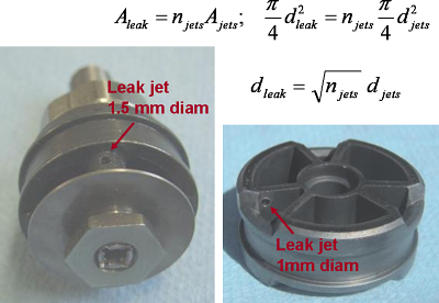
d.leak [=] Valve port leak jet diameter in millimeters. Valves using a leak jet typically have only one jet on one port. In that case the input is simply the jet diameter. If the valve has multiple leak jets on a single port the "effective" jet diameter is [d.leak= sqrt(N.jets) d.jet] where N.jets is the number of leak jets on a single valve port. If the valve has leak jets on multiple ports the input is "Nport x Deff" where Nport specifies the number of ports with a leak jet and D.eff is the "effective" diameter of leak jets on that port. For example:
-
"1.5" specifies a single leak jet on only one valve port with a 1.5 mm diameter
-
"3x0.5" specifies a valve where three of the valve ports have a 0.5 mm leak jet
-
-
d.thrt [=] The effective flow diameter of any flow restriction in the
 valve port. For free flowing valves, like the KTM valve above, d.port and w.port
define the valve port flow area and there is no
restriction. In that case both D.thrt and N.thrt are set
to zero. For valves with port restrictions, like the Honda and
Marzocchi valves above, D.thrt defines the
minimum flow area or restriction in the valve port. Example calculations to determine d.thrt for
trapezoid and parabolic shaped port restrictions are shown below.
valve port. For free flowing valves, like the KTM valve above, d.port and w.port
define the valve port flow area and there is no
restriction. In that case both D.thrt and N.thrt are set
to zero. For valves with port restrictions, like the Honda and
Marzocchi valves above, D.thrt defines the
minimum flow area or restriction in the valve port. Example calculations to determine d.thrt for
trapezoid and parabolic shaped port restrictions are shown below.
-
N.thrt [=] The number of valve port restrictions. For the Honda and Marzocchi valves above each port has one throat restriction so N.port and N.thrt are both equal to four. In general N.thrt and N.port have the same value. ReStackor uses the separate N.thrt input for special cases where multiple side ports on the valve feed one valve port.
The parameters d.port, w.port and N.port define the valve port flow area. The additional parameters D.thrt and N.thrt handle special cases where flow restrictions in the port further restrict the flow. The parameters N.thrt and D.thrt can also be used to model valves using multiple side ports to feed a single valve port.
![]()
Settings
The settings input block describe the clicker position and suspension velocity used for the calculation.
-
n.click [=] The clicker setting. n.click specifies the number of clicks out from full closed.
-
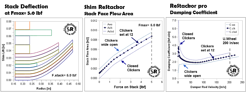
F.stack [=] Force applied to the shim stack face. Shim ReStackor calculations display the stack structure, compute the shim edge lift and the stack face flow area at the value specified by F.stack in [lbf].
-
u.wheel [=] The maximum suspension shaft velocity in inches per second. ReStackor pro calculations compute the damping force as a function of suspension velocity up to the value specified by u.wheel. If the fluid forces on the shim stack produce a force greater than the value specified by F.stack the calculations internally adjust F.stack to produce a stack deflection consistent with the value requested for u.wheel. However, the stack deflection drawing is drawn at the value specified by F.stack.
-
Separate inputs for F.stack and u.wheel allow the stack structure to be displayed at a low applied force, like examining where a crossover gap closes, while the damping force is computed at a higher suspension velocity.
The relationship of bump height, bike speed and suspension velocity for different wheel sizes are given here. With an estimate of the suspension velocity, say a three inch bump hit a 30 mph, you can design crossover gaps, backing shims or the stack taper to produce a specific damping force at the suspension velocity produced by a given bump height.
![]()